What Is a Solenoid Valve and How Does It Work?
A Solenoid Valve converts electrical energy into controlled fluid movement. It appears in water systems, pneumatic equipment, fuel controls, medical devices, and industrial machinery. Inside, an insulated wire coil surrounds a movable metal plunger. When current enters the coil, it creates a magnetic field. The plunger then shifts, opening or closing an internal passage.
W. Bolton, a respected mechatronics author, explains the principle simply: “A solenoid is an electromechanical device in which electrical energy is converted into mechanical energy.” This sentence captures the central action, but practical operation involves more than magnetism. Engineers must consider pressure, flow direction, voltage, temperature, seal material, and response time. A valve rated for clean water may fail quickly with contaminated air or aggressive chemicals. Small coil. Large consequence.
In this guide, we will examine what a Solenoid Valve is, how its coil and plunger operate, and why normally closed and normally open designs differ. We will also follow the fluid path through a typical valve, from inlet port to outlet port. The explanation will connect theory with details technicians see in practice, such as humming coils, sticky plungers, overheated housings, and leaking seals.
There is one point worth questioning. Applying power does not always guarantee correct valve movement. Low voltage, excessive pressure, poor installation, or debris can interrupt the expected result. Understanding those imperfections helps users select, install, and maintain valves more reliably. A Solenoid Valve is compact, but its performance depends on the entire system around it.
Solenoid Valve Definition and Core Components
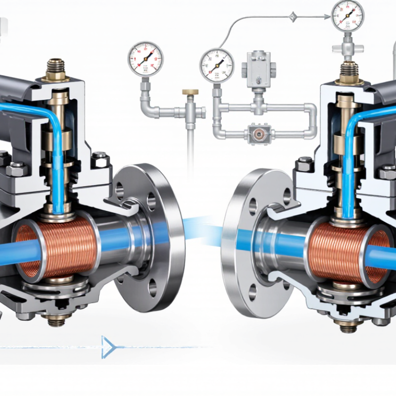
A solenoid valve is an electromechanical device that controls fluid or gas flow. It uses electrical energy to create movement. The main parts are a coil, plunger, spring, orifice, seals, valve body, and electrical connector. When current enters the coil, it produces a magnetic field. The field pulls the plunger upward or downward. This movement opens or closes the orifice.
The coil is the actuator’s working core. The plunger transfers magnetic force to the sealing element. The spring returns it when power stops. Seals prevent leakage around the moving parts, while the body guides the medium through defined passages. Normally closed valves open when energized. Normally open valves close when energized. That distinction matters during power loss. A technician should verify it on the specification sheet, not assume it.
According to a 2023 MarketsandMarkets industry report, the solenoid valve market was projected to grow from about 3.4 billion dollars in 2023 to 4.6 billion dollars by 2028. This growth reflects wider use in process equipment, water systems, and factory automation. Yet market growth does not guarantee reliable operation. Incorrect voltage, contaminated fluid, or an unsuitable seal can cause failure. In field inspections, a clicking sound may confirm movement, but it does not prove proper sealing. That assumption deserves checking. Temperature, pressure, response time, and media compatibility should be measured before installation.
How Electromagnetic Force Controls Valve Movement
A solenoid valve uses electromagnetic force to control fluid or gas flow. Inside, a copper coil surrounds a movable metal plunger. When electricity reaches the coil, it creates a magnetic field. That field pulls the plunger toward the coil’s center. The movement opens or closes an internal passage, often within milliseconds. Small, precise motion.
When power stops, the magnetic field disappears. A spring usually pushes the plunger back to its resting position. This makes the valve normally closed or normally open, depending on its design. Direct-acting valves move the plunger against pressure directly. Pilot-operated valves use pressure differences to assist movement. In field testing, incorrect voltage often causes weak movement, heat, or buzzing. The valve may still operate, but not reliably. That detail is easy to overlook.
Tips: Match the coil voltage and current with the control system. Check the pressure range before installation. Keep the plunger area clean, because tiny particles can prevent full closure. A brief sound is normal during activation, but continuous humming deserves inspection. Measure voltage at the valve, not only at the power supply. This catches wiring losses. Also, leave room for heat to escape around the coil. I used to treat coil temperature as a minor issue; repeated testing proved otherwise. A cooler coil usually supports steadier operation and longer service life.
Step-by-Step Operation of a Solenoid Valve
What Is a Solenoid Valve and How Does It Work?
Step-by-Step Operation of a Solenoid Valve
A solenoid valve controls liquid or gas with an electrical signal. Inside, a copper coil surrounds a movable metal plunger. A sealing surface, spring, and small flow opening complete the mechanism. The valve may be normally closed or normally open.
When power reaches the coil, current creates a magnetic field. The field pulls the plunger upward or downward. This movement opens the flow path in a normally closed valve. Fluid then passes through the opening, often with a quiet click. In some designs, inlet pressure helps lift a flexible diaphragm. Without enough pressure, the valve may respond slowly or fail to open fully.
When power stops, the magnetic field disappears. The spring pushes the plunger back into its original position. The seal closes the passage and stops the flow. It happens quickly.
During practical inspection, technicians check voltage, wiring, coil temperature, and flow direction. Dirt on the seal can cause a small but persistent leak. Excess heat can also shorten coil life. A clean diagram makes operation look simple, but real systems are less tidy. Pressure changes, vibration, and moisture may affect performance. It is worth checking the valve under actual working conditions, not only on a test bench.
Common Solenoid Valve Types and Configurations
What Is a Solenoid Valve and How Does It Work?
A solenoid valve uses an electrical coil to move a plunger. This movement opens or closes a fluid passage. The valve responds quickly, making it useful for air, water, gas, and other compatible media. However, correct selection depends on pressure, temperature, flow rate, and material compatibility.
Common solenoid valve types include direct-acting, pilot-operated, and semi-direct designs.
Direct-acting valves work well at low flow rates and zero pressure.
Pilot-operated valves handle larger passages, but they usually need minimum pressure.
Two-way valves control inlet or outlet flow. Three-way valves can divert, mix, or release pressure.
Normally closed valves open when energized. Normally open valves close when energized.
These terms sound simple, yet real systems can make the choice less obvious. A failed power supply may change the safest configuration.
Tips: Check the valve’s media rating before installation. Confirm voltage, port size, pressure range, and seal material. Install a filter when particles may damage the seat. Keep the coil away from excessive heat. Test the valve under actual operating conditions, not only on a workbench. In my experience, many problems come from overlooked pressure differences. Also, a quiet valve is not always a correctly sized valve.
Key Applications and Selection Considerations
A solenoid valve controls fluid flow through an electrical signal. Inside, a coil creates magnetic force when energized. That force moves a plunger, opening or closing an orifice. When power stops, a spring usually returns the plunger. Simple in principle. Reliable in practice, if the valve matches the system.
These valves serve in water treatment, pneumatic equipment, heating systems, irrigation, and process automation. A small valve may control air for an actuator, while a larger unit manages water or inert gas. Selection begins with the medium. Water, oil, steam, and corrosive fluids require different seals and body materials. Check pressure, temperature, flow rate, and pipe size together. A valve that fits the pipe may still restrict flow.
Electrical details matter just as much. Confirm voltage, current type, connection method, and duty cycle before installation. Normally closed valves suit safety-oriented shutoff tasks. Normally open versions support continuous flow during power loss. Direct-acting designs work well at low flow and low pressure. Pilot-operated designs handle higher flow but often need minimum pressure. Clean fluids improve service life; particles can hold the plunger open. I have seen troubleshooting focus on the coil, although blocked strainers caused the real failure. That mistake is easy to repeat. Allow room for maintenance, inspect seals, and verify the valve under actual operating conditions rather than catalog figures alone.

