Auto Repair Shop In Plainfield, IL
An Impulse Voltage Generator produces brief, controlled high-voltage pulses for testing electrical insulation. Engineers use these pulses to imitate lightning strikes and switching surges. The equipment helps assess transformers, cables, bushings, insulators, and other high-voltage components. Its purpose is practical: reveal weaknesses before a failure occurs in service.
The operating principle is straightforward, although the hardware is not. Several capacitors charge in parallel through resistors and charging circuits. Spark gaps then trigger almost simultaneously. The capacitors discharge in series, creating a much higher voltage at the test terminal. Wavefront and wave-tail resistors shape the pulse. Measuring systems record the result through a voltage divider and oscilloscope. A typical lightning impulse may rise within microseconds, then decay more slowly.
Small timing errors matter.
Experienced test engineers also control grounding, room clearance, humidity, and measurement bandwidth. These details can influence the recorded waveform. IEC 60060 guidance supports repeatable high-voltage testing, but standards do not replace careful judgment. A generator may produce an impressive peak voltage while still delivering an unsuitable waveform. That distinction is easy to miss. It is also where inexperienced testing can become misleading.
This article explains the main parts of an Impulse Voltage Generator and follows the energy path from charging to discharge. It also considers practical limitations, safety interlocks, waveform measurement, and common testing mistakes. The explanation remains focused on engineering use. Some designs vary considerably, so simplified diagrams should not be treated as complete operating instructions. Real systems require qualified personnel, calibrated instruments, and documented procedures.
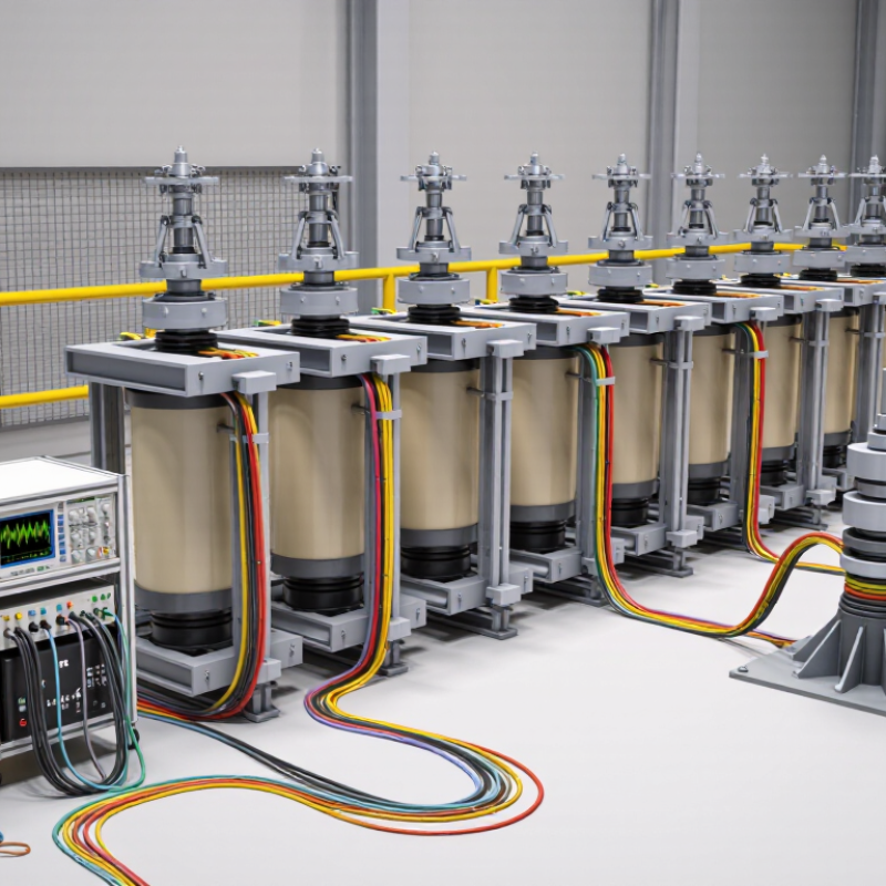
An impulse voltage generator is a laboratory system that produces a short, high-voltage surge. Engineers use it to test insulation in transformers, cables, switchgear, and other power equipment. The surge imitates lightning or switching events that can stress electrical insulation during service. It is not a continuous power source. It delivers energy briefly, then stops.
The system usually charges several capacitors in parallel. Spark gaps then connect them in series, creating a much higher voltage. Resistors and capacitors shape the rising and falling edges of the pulse. According to IEC 60060-1, the standard lightning impulse waveform is 1.2/50 microseconds. Its front rises quickly, while the tail decays more slowly. IEEE Std 4-2013 defines measurement methods for these high-voltage tests. A voltage divider records the pulse, and an oscilloscope displays its actual shape. Small errors matter.
In practical testing, engineers compare the measured waveform with tolerance limits before accepting results. The test object may show puncture, surface flashover, or no visible damage. CIGRE technical guidance emphasizes controlled grounding, shielding, and measurement quality for reliable impulse testing. The generator’s design looks simple, but stray inductance can distort the pulse. That detail is easy to underestimate. Experienced technicians therefore inspect connections, calibration records, and room conditions before energizing the circuit. Perfect waveforms are rare, and that should encourage careful review rather than careless confidence.
An impulse voltage generator produces a brief, high-voltage surge for testing electrical insulation. Its main components work together in a carefully controlled sequence. A charging unit supplies direct current to one or more energy-storage capacitors. These capacitors hold electrical energy until the firing circuit releases it. The charging resistor limits current and improves operator safety during preparation. A voltage divider monitors the charging level without exposing measuring instruments to the full voltage. This detail matters.
The switching system usually includes spark gaps or another fast electronic trigger. Once activated, it connects the charged capacitors to the test circuit. Series resistors control the rising time, while discharge resistors shape the voltage tail. Together, they create a specified impulse waveform instead of an uncontrolled arc. A test object connects to the output terminal, and a grounded return path completes the circuit.
Protective enclosures, interlocks, and emergency discharge devices reduce accidental exposure. Real setups are less tidy than diagrams. Stray inductance, poor grounding, and humid surfaces can distort results. I have found that careful cable placement often matters more than expected.
The measuring system may include an oscilloscope, a calibrated divider, and recording software. These tools verify peak voltage, duration, and waveform consistency. A perfect waveform is an assumption, not a guarantee. Regular calibration and visual inspection remain essential.
An impulse voltage generator produces a short, controlled surge that imitates lightning or switching events. Its main parts are charging resistors, capacitors, spark gaps, and wave-shaping resistors. During charging, the capacitors connect in parallel and store electrical energy at high voltage. A trigger then fires the spark gaps. The capacitors rapidly reconnect in series, creating a much higher output voltage.
The pulse moves through the test circuit in microseconds. A front resistor controls how quickly the voltage rises. A tail resistor controls how slowly it falls. Together, they shape the familiar impulse waveform. Measurement requires a calibrated voltage divider, fast recording equipment, and carefully positioned grounding conductors. Small layout changes can affect the result. That detail is easy to underestimate.
In practical high-voltage laboratories, operators inspect insulation, clearances, and discharge paths before charging. Safety interlocks and visible warning systems are essential. The ideal waveform is rarely perfect. Stray capacitance, humidity, and spark-gap timing can distort it. Engineers compare the measured curve with recognized test requirements, then adjust the circuit. A simplified explanation says the capacitors “add” their voltages, but real systems also lose energy through resistance, radiation, and leakage. Careful testing makes those imperfections measurable.
An impulse voltage generator creates a brief, high-voltage surge for testing electrical insulation. It stores energy in capacitors, then releases it through a controlled switching circuit. The result is a fast-rising pulse, similar to a lightning strike or switching event.
In a testing laboratory, technicians connect the generator to equipment such as transformers, cables, bushings, or switchgear. They apply a defined impulse waveform and measure the equipment’s response with voltage dividers, current sensors, and digital recording systems. The test may reveal insulation breakdown, flashover, internal discharge, or unexpected deformation of the waveform. A typical setup requires careful grounding, physical barriers, interlocks, and remote operation. Safety distances matter because the stored energy remains dangerous after the pulse ends. Testing teams often compare results with applicable IEC or IEEE requirements. However, a compliant waveform does not always prove perfect field performance. Moisture, contamination, aging, and installation errors can change real-world behavior.
Tips: Check the generator’s calibration before testing. Inspect cables and connections closely. Keep the test area dry and clearly controlled. Record temperature, humidity, charging voltage, and waveform data. Small details matter. A perfect-looking trace can still hide a loose connection or a poorly positioned sensor. Technicians should review unusual results instead of repeating the test mechanically. That extra reflection often prevents a misleading conclusion.
What Is an Impulse Voltage Generator and How Does It Work?
An impulse voltage generator stores energy in capacitors, then releases it through controlled switching. The circuit creates a rapid voltage surge, similar to lightning or switching events. Its performance depends heavily on capacitance, charging voltage, and the resistance-inductance network shaping the waveform. Small changes matter. A poorly selected resistor can lengthen the front time or produce unwanted oscillation. The connected test object also affects the result, because its capacitance and leakage path change the discharge behavior.
Measurement quality is equally important. Probe bandwidth, grounding, cable length, and voltage-divider accuracy can distort the recorded peak. A waveform may look acceptable while the measuring system hides a sharp overshoot. Humidity is unforgiving. Moisture on insulators can increase leakage, weaken insulation, and trigger surface flashover. Temperature, dust, electrode spacing, and enclosure design deserve regular checks. In practical testing, calculations provide direction, but measured results should control final adjustments.
Safety begins before charging. The enclosure should restrict access, provide visible warning signals, and include reliable interlocks. Grounding must remain short, strong, and regularly inspected. After each test, capacitors need an automatic discharge path, followed by a verified zero-voltage check. Operators should keep safe clearance from exposed conductors and use procedures suited to the stored energy. One detail is easy to overlook: residual charge can remain after the main supply is disconnected. That mistake can be serious. A documented inspection record, calibrated instruments, and independent waveform review make the system more dependable, although no setup is flawless.
| Data Dimension | Typical Value or Range | Technical Meaning | Main Performance or Safety Effect |
|---|---|---|---|
| Basic operating principle | Capacitor charging followed by rapid series discharge | Multiple charged capacitor stages are connected in series by triggered or self-triggered spark gaps. | The output can reach a high voltage within microseconds, creating a controlled test impulse. |
| Common circuit type | Marx-type impulse generator | Capacitors are charged in parallel and discharged in series. | The theoretical output is approximately the number of stages multiplied by the charging voltage, before circuit losses. |
| Typical number of stages | 3–20 stages in laboratory systems | Each stage normally includes a capacitor, charging resistor, damping or grading components, and a spark gap. | More stages increase voltage capability but also increase insulation, synchronization, maintenance, and footprint requirements. |
| Charging voltage per stage | Approximately 10–100 kV, depending on the design | The direct-current voltage used to charge each stage before triggering. | Higher charging voltage increases output amplitude and stored energy, raising insulation and arc-flash hazards. |
| Impulse voltage amplitude | Approximately 100 kV to above 1 MV for laboratory equipment | The peak value of the generated transient voltage at the test object or output terminal. | Higher amplitude increases electrical stress and the required clearances, creepage distances, shielding, and enclosure strength. |
| Standard lightning impulse shape | 1.2/50 μs nominal waveform | The front time is approximately 1.2 μs and the time to half-value on the tail is approximately 50 μs. | Waveform accuracy affects comparability between tests and the validity of insulation performance results. |
| Standard switching impulse shape | 250/2500 μs nominal waveform | A much slower impulse used to represent switching-related overvoltages in high-voltage systems. | Longer duration can produce different dielectric, surface-discharge, and thermal effects than a lightning impulse. |
| Stage capacitance | Typically tens to hundreds of nanofarads per stage | The capacitance determines how much charge and energy can be stored at the selected charging voltage. | Larger capacitance can improve load capability but increases stored energy, discharge current, and hazard severity. |
| Stored energy relationship | E = ½CV² per capacitor | Stored energy rises linearly with capacitance and with the square of charging voltage. | A small increase in charging voltage can cause a substantial increase in shock, arc-flash, and mechanical failure risk. |
| Wave-shaping resistors | Front resistor and tail resistor selected for the test circuit | The front resistor primarily controls rise time, while the tail resistor primarily controls decay time. | Incorrect resistance values can cause excessive overshoot, an incorrect waveform, resistor overheating, or excessive stress on the test object. |
| Load capacitance | Depends on the test object, divider, leads, and stray capacitance | The generator and the test setup form a combined transient circuit. | A higher load capacitance generally reduces peak voltage and changes front and tail times unless the circuit is retuned. |
| Generator internal inductance | Should be minimized through compact construction and short current paths | Inductance is introduced by conductors, connections, gaps, and return paths. | Excess inductance slows the impulse front and can produce ringing or voltage overshoot. |
| Spark-gap pressure and spacing | Adjusted according to the required breakdown and synchronization voltage | Breakdown depends on gap distance, gas pressure, humidity, electrode condition, and applied voltage. | Unstable gaps cause timing jitter, incomplete erection of stages, or unintended triggering. |
| Voltage measurement | High-voltage resistive, capacitive, or combined divider | A divider scales the impulse to a measurable level while preserving the waveform as accurately as possible. | Divider bandwidth, response time, calibration, and grounding directly affect measurement accuracy and operator safety. |
| Humidity and air density | Environmental conditions must be recorded and controlled where possible | Temperature, atmospheric pressure, and humidity affect air breakdown strength and surface leakage. | Changing conditions can alter spark-gap firing, flashover probability, and test repeatability. |
| Grounding and return path | Low-inductance, short, dedicated return connection | The return path completes the impulse circuit and controls the voltage distribution during the transient. | Poor grounding can create dangerous touch voltages, measurement errors, electromagnetic interference, and unexpected flashover. |
| Clearance and creepage | Determined by peak voltage, insulation medium, pollution, altitude, and applicable standards | Clearance is the shortest air distance; creepage is the shortest distance along an insulating surface. | Insufficient distances can cause air breakdown, surface tracking, fire, equipment damage, or fatal electric shock. |
| Stored-energy discharge time | Must be verified before access; automatic discharge is recommended | Capacitors can retain hazardous charge after the charging supply is switched off. | Bleeder resistors, grounding sticks, interlocks, and a documented zero-voltage check are essential safety measures. |
| Safety controls | Interlocked enclosure, warning indicators, emergency stop, barriers, and controlled access | Engineering controls prevent energization when personnel could enter the high-voltage area. | Interlocks and barriers reduce the likelihood of accidental contact, unintended triggering, and unauthorized operation. |
| Applicable test practice | Use the current edition of relevant high-voltage test standards | Standards define impulse parameters, measurement methods, tolerances, calibration, and safety practices. | Following the applicable standard improves repeatability, traceability, personnel protection, and acceptance of test results. |
Note: The values shown are representative engineering ranges rather than universal equipment ratings. Actual limits depend on the generator design, test object, laboratory layout, environmental conditions, and applicable safety standards.
Plainfield, 60585, 60544, 60586, Naperville, 60564, Bolingbrook, 60490, 60440, Romeoville, 60446, Will, Kendall, DuPage, Counties. Our auto repair shop in Plainfield, IL, has been serving the local area plus all surrounding Chicagoland since 1978.
• Computer Diagnostic • Brake Shop • Engine Replacement • Transmission Rebuild • Clutch Replacement • Differential Rebuild • Suspension Shop • Steering • Shocks & Struts • Heating & Cooling • Electrical • Exhaust Shop • Catalytic Converter Replacement • Alignment • Domestic & Foreign Vehicle Service • Auto Repair In Plainfield, IL • Auto Repair Shops Near Me • Towing Service Near Me